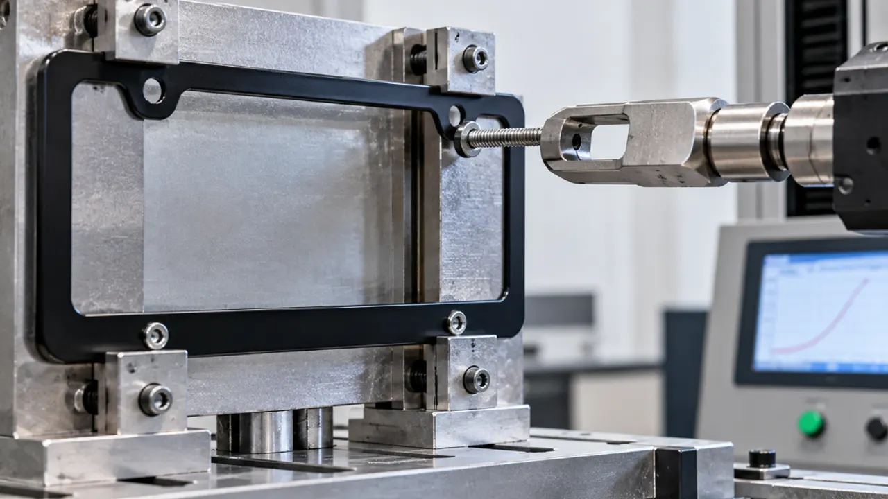
A license plate frame mounting hole pull-out test measures how the hole region behaves when a fastener loads it in a defined direction. The result depends on the frame material and thickness, hole or slot geometry, washer and screw head, edge distance, support, loading rate, and whether the sample is new or environmentally conditioned.
Peak load alone is not enough. A useful result also identifies how the sample failed: hole elongation, cracking, washer pull-through, insert pull-out, local bending, fastener failure, or gradual slip. Those modes lead to different design decisions.
Define the Load Direction Before Building the Fixture
“Pull-out” can describe several different loads. Pulling the fastener perpendicular to the frame tests head or washer pull-through and local bending. Pulling the frame parallel to its plane can test bearing strength, slot elongation, and edge tear-out. Pulling a threaded insert along its axis evaluates insert retention.
| Load direction | Likely failure | What it can represent |
|---|---|---|
| Perpendicular to frame face | Head or washer pull-through, local cracking or bending | Separation from a supporting mount |
| In-plane toward an outer edge | Bearing deformation, slot elongation, edge tear-out | Assembly movement or directional service load |
| Axial extraction of insert | Insert release or boss fracture | Retention of molded or installed threaded hardware |
Name the direction on the drawing or fixture sketch. Two labs can use the same word and produce unrelated values if one pulls through the face while the other pulls toward the edge.
Use Production-Representative Holes and Finished Parts
The sample should include the real hole or slot process, local radius, edge distance, section thickness, ribs or bosses, finish, and any insert. Drilled laboratory holes may not reproduce molded knit lines, stamped burrs, plating buildup, or production stress.
When different mounting positions use different geometry, test each critical location. A top slot near a thick logo bar may not behave like a lower round hole in a narrow section. The mounting-hole spacing method helps document location, but strength testing also needs local geometry and load direction.
Specify the Fastener, Washer, and Tightening Condition
A large washer distributes load over more area and can raise the apparent pull-through load. A small screw head concentrates stress. Countersunk heads, caps, rubber washers, and spacers change the contact pattern again. Record head diameter, washer dimensions, fastener type, and assembly order.
If the test includes initial tightening, define the method. Overtightening can pre-crack plastic or dish thin metal before the tensile load begins. If the objective is the frame material alone, the setup may use a standardized loading pin instead—but that result should not be presented as the performance of a production screw stack.
The site’s washer and spacer guidance explains how contact area and stack height affect installation.
Design the Fixture to Avoid a False Failure
Support the frame far enough from the hole to permit the intended local deformation, but not so far away that the entire side rail becomes the test specimen. Clamp locations, support opening, grip shape, and alignment should be documented. Misalignment can add bending and reduce repeatability.
The pulling axis should pass through the intended load path. Protect the sample from slipping in the grip without crushing it. For flexible frames, a fixture that forces the part flat may change stress around the hole; decide whether free geometry or installed geometry is relevant.
Control the Loading Rate and Data Collection
Use a calibrated force-measurement system and a defined crosshead or loading rate. Polymers can respond differently at different rates, while thin metal may yield progressively. Record force and displacement throughout the test when possible, not only the final peak.
The force-displacement curve can distinguish a sudden brittle crack from gradual slot elongation. It also shows whether the assembly slipped in the fixture before the part failed.
Conditioned Tests Need Their Own Results
Heat, cold, humidity, UV exposure, and chemical contact can change a material or finish. If conditioned pull-out strength is required, state the conditioning method, recovery time, and test temperature. Do not merge conditioned and unconditioned values into one average.
A vibration sequence can be followed by a residual pull-out test when the requirement calls for it. That combination can reveal crack initiation or hole wear that is not obvious by eye. Keep the initial strength, post-conditioning strength, and failure modes separately reported.
Choose Acceptance Criteria From the Joint Requirement
A minimum peak force may be part of the requirement, but it should not stand alone. Consider maximum permanent hole growth, crack length, insert movement, and whether the plate remains retained. A frame that carries a high peak load after severe slot elongation may still be unsuitable.
Set the value from the design load, safety factor, installation, material variability, and customer specification. There is no credible universal pull-out number for all license plate frames.
What the Report Should Include
- Part, material as specified, finish, lot, cavity or tool, and drawing revision.
- Hole identity, dimensions, edge distance, and local section.
- Fastener, washer, spacer, insert, and tightening condition.
- Fixture drawing, supports, grips, alignment, and load direction.
- Loading rate, environment, conditioning, and sample quantity.
- Peak load, displacement data, failure mode, and failure location.
- Photos before and after testing.
- Acceptance criteria and disposition for each sample.
Common Test Errors
- Using a washer that is larger than the production hardware without reporting it.
- Pulling at an angle because the fixture and hole are misaligned.
- Clamping so close to the hole that normal deformation is blocked.
- Testing machined holes instead of production geometry.
- Reporting fastener failure as frame pull-out strength.
- Averaging different hole types or conditioned states together.
Frequently Asked Questions
Is pull-out testing the same as screw torque testing?
No. Torque testing evaluates rotational installation or thread behavior. Pull-out applies a tensile or in-plane force to the assembled hole region. One does not replace the other.
Should slotted holes be tested differently from round holes?
Often yes. Slot direction, end radius, washer coverage, and load direction can change the failure. Test the orientation that matches the intended joint.
Can one sample be tested at all four holes?
A destructive test at one hole can distort the frame and affect later results. Use separate samples or a validated sequence that prevents one test from influencing another.
What if the screw breaks before the frame fails?
Report it as a fastener-limited result, not the frame’s ultimate pull-out strength. Decide whether the joint has still met the functional requirement or whether another setup is needed to characterize the frame.