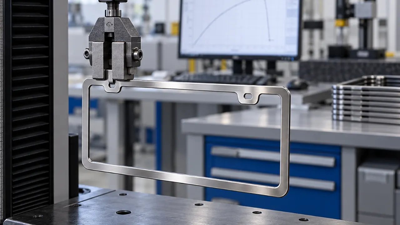
A license plate frame vibration test should evaluate the installed system: frame, plate, fasteners, washers or spacers, holder, and representative mounting surface. Testing a loose frame on a shaker may reveal material resonance, but it does not show whether the real assembly loosens, cracks, rattles, or rubs the vehicle.
There is no single vibration profile that automatically represents every passenger car, truck, motorcycle, trailer, or off-road vehicle. Define the environment, mounting position, frequency content, acceleration, axes, duration, and acceptance criteria before the test begins.
Decide What the Test Is Supposed to Prove
A vibration program may be used to find resonance, compare two frame designs, assess mounting security, expose fatigue at thin sections, or check whether decoration survives an assembly test. Those goals need different inputs and observations.
| Test objective | Important setup choice | Useful output |
|---|---|---|
| Find resonant behavior | Controlled frequency sweep with monitored response | Resonant frequencies and amplification locations |
| Check cumulative fatigue | Defined sine dwell or random exposure in relevant axes | Cracks, permanent deformation, or attachment damage |
| Check fastener retention | Production hardware and representative joint stack | Rotation, preload or torque change, and displacement |
| Check rattle and contact wear | Plate, pads, frame, and vehicle-side surface included | Noise, witness marks, fretting, and finish damage |
The existing troubleshooting advice for license plate frame rattle identifies field symptoms. A laboratory vibration test goes further by controlling the input and documenting how the assembly changes.
Reproduce the Mounting Stack
Use the intended plate size, hole pattern, screw head, washer, spacer, nut or insert, tightening method, and supporting bracket. Record fastener material and thread engagement when specified. A wide washer on a slot behaves differently from a small screw head, and a rigid aluminum fixture behaves differently from a flexible plastic vehicle bracket.
The fixture should be stiff enough not to dominate the response, yet the interface must represent the real attachment. If the actual bracket is an important part of the system, include it rather than replacing it with an unrealistically solid plate. Photograph and dimension the setup so another lab can reproduce it.
Choose Sine, Random, or a Combined Sequence
Sinusoidal vibration applies a controlled frequency that can be swept or held. It is useful for finding resonances and studying response at known frequencies. IEC 60068-2-6 provides a standardized sinusoidal vibration procedure for specimens tested at specified severities.
Random vibration distributes energy across a frequency range and can represent stochastic loads found in transport and vehicle environments. IEC 60068-2-64 addresses broadband random vibration. Neither document supplies a universal license plate frame severity; the relevant specification still has to define the profile and acceptance limits.
A program may use a low-level resonance search, durability exposure, and final search to detect changes. Do not copy a severe electronics or aerospace profile into a frame program merely because it is available.
Test the Relevant Axes
A rear-mounted frame may respond differently front-to-back, side-to-side, and vertically. Front-to-back input can drive contact with the plate or body. Vertical input may load screw slots and bottom supports. Side-to-side input can expose clearance in elongated holes.
Define the coordinate system on the drawing or setup photo. If the frame is rotated between axes, maintain the same assembly and fastener condition unless the procedure states otherwise. Reassembly between axes can reset looseness and hide cumulative damage.
Record the Starting Condition
Before vibration, inspect dimensions, flatness, cracks, decoration, hole edges, fastener seating, and plate visibility. Mark screw positions with a suitable witness mark when rotation is part of the evaluation. Record tightening method and any measured torque or preload without claiming that removal torque equals original preload.
Capture baseline photos of mounting holes, inner corners, lower bars, raised lettering, and contact points. A small bright rub mark after testing is easier to interpret when the same location is documented before exposure.
Watch the Test Without Changing It
Monitor fixture integrity, abnormal noise, contact, fastener motion, and specimen displacement. Accelerometers or other sensors should be placed and mounted according to the test plan; their mass and wiring should not change a lightweight frame’s behavior.
If a screw backs out or a section cracks, record the time and input condition. Stopping for safety is sensible, but retightening the part and continuing without a documented disposition destroys the original result.
Inspect More Than Visible Breakage
Post-test checks should include:
- loose, rotated, or displaced fasteners;
- elongated holes, cracks, whitening, or local yielding;
- frame or plate movement relative to the fixture;
- finish wear, fretting, and vehicle-side contact marks;
- loss of logo, insert, clip, or screw-cap retention;
- permanent bow, twist, or opening change;
- plate obstruction or lighting interference after movement.
Repeat any defined functional fit or rattle check. The loose-screw prevention factors are useful inspection points, but the test report must keep observed evidence separate from assumed cause.
Set Acceptance Criteria Before Testing
Possible criteria include no fracture, no fastener loss, no specified rotation or displacement beyond a limit, no loss of plate retention, no new sharp edge, no unacceptable rattle, and no visible information covered. Define whether cosmetic rub marks are acceptable and how they are rated.
“No damage” is too vague. A design review needs named locations, measurable limits where practical, and an approved visual standard for appearance. For mounting holes and fastener contact, link the vibration result to the released hole-layout requirement.
What the Report Should Show
Include sample and lot identity, drawing revision, material and finish as specified, complete mounting stack, fixture drawing or photo, tightening method, input profile, control point, axes, duration, interruptions, monitoring, before-and-after data, failures, and final disposition. Save raw controller data when the program requires it.
If the setup deviates from the referenced procedure, state the deviation plainly. A precise report with a justified custom profile is more useful than a standard name attached to an undocumented setup.
Frequently Asked Questions
How long should a license plate frame vibration test run?
Duration depends on the objective, input severity, axes, and correlation plan. A cycle count or number of hours has no standalone meaning without the rest of the profile.
Should the license plate be installed during the test?
Yes when the goal is installed assembly behavior. The plate changes mass, contact, and clamping. A frame-only test may still be useful for a material or resonance study if that scope is stated.
Can vibration testing prove the frame will never rattle?
No. It demonstrates behavior under the tested setup and profile. Vehicle bracket condition, installation, road input, temperature, and maintenance can differ in service.
Is random vibration always more realistic than sine testing?
No. Random input can represent broad operational loads, while sine testing is valuable for resonance search and defined periodic excitation. Use the method that answers the intended question.