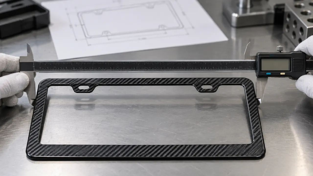
A useful license plate frame dimensional tolerance controls the features that affect plate fit, mounting, visibility, and assembly. It does not place the same tight plus-or-minus limit on every line of the drawing. Start by identifying the functional interfaces, choose datums that reproduce how the frame is located, and state both the tolerance and the inspection method.
The nominal dimension tells you where the feature is intended to be. The tolerance tells you how far production may vary and still be acceptable. That limit should come from a real fit or appearance requirement—not from the number of decimal places used in CAD.
Which Dimensions Actually Need Tight Control?
Four areas usually deserve the closest attention: the plate-retention geometry, visible opening, mounting pattern, and installed contact surface. Their exact limits remain model-specific, but their functions are consistent.
| Feature | What variation can change | Typical control approach |
|---|---|---|
| Visible opening | Plate text or stickers may be covered; gaps may look uneven | Minimum opening or profile relative to defined datums |
| Plate pocket or channel | The plate may bind, rattle, or fail to seat | Width, height, depth, and corner conditions with clear measurement locations |
| Mounting holes or slots | Screws may misalign or load the frame unevenly | Hole size plus position relative to functional datums |
| Rear contact features | The frame may rock, bow, or rub the vehicle | Height, profile, flatness, or contact-point limits |
| Logo and border location | Branding may look off-center or reduce the opening | Position from the opening, not only from an uncontrolled outer edge |
The opening-size specification method and mounting-hole measurement method help separate these functional dimensions before tolerance values are assigned.
Choose Datums From How the Frame Works
A datum is a theoretically exact reference used to locate or orient other features. On a frame, the primary datum might be a stable rear mounting surface, while secondary and tertiary datums may come from mounting holes, a center plane, or a functional edge. The right choice depends on how the part is held and assembled.
Using a decorative outer edge as the main reference can create misleading results if that edge is molded, polished, or intentionally styled. A hole pattern measured from an unstable cosmetic edge may pass the report and still miss the vehicle mount. Let the assembly establish the datum scheme.
Use Bilateral, Unilateral, and Geometric Limits Deliberately
A bilateral tolerance allows variation in both directions around nominal. A unilateral tolerance allows variation mainly in one direction. The latter can be especially useful for clearance: a visible opening may have a minimum acceptable size, while a plate channel may have a maximum condition that must never bind the largest permitted plate.
Geometric controls can describe position, profile, flatness, or perpendicularity when ordinary coordinate dimensions leave the intent unclear. ASME Y14.5 supplies a common language for dimensioning and geometric tolerancing, but citing it is not a substitute for choosing the correct datums, values, and verification method for the frame.
The related license plate frame CAD drawing checklist shows where tolerances, sections, material notes, and artwork information belong in the controlled product definition.
Build the Tolerance Stack Around the Plate and Vehicle
One dimension rarely acts alone. The installed clearance may depend on the largest plate, smallest frame pocket, coating buildup, hole position, washer diameter, screw location, and vehicle recess. Review the unfavorable combination, not just the nominal assembly.
For example, an opening can look generous at nominal size but become restrictive when the frame opening is at its minimum and the plate is at its maximum. At the other extreme, excessive clearance can make the border look uneven or allow movement before tightening. A tolerance stack makes both limits visible before tooling is approved.
Match the Inspection Tool to the Characteristic
Calipers work well for accessible widths, heights, and simple hole diameters, but they are easy to misuse on tapered walls or flexible plastic. Pin gauges may clarify hole size. A height gauge, optical system, coordinate measuring machine, fixture, or profile comparison may be better for feature location and complex molded geometry.
Record where the measurement is taken. “Opening width” is ambiguous when front lip, rear pocket, and drafted molding wall all give different numbers. The report should state the characteristic number, requirement, actual result, tool or method, sample identity, and disposition.
Condition Flexible Parts Before Measurement
Plastic and thin metal frames can change shape with handling, temperature, humidity, packaging pressure, and fixture force. Define whether the part is inspected free-state, lightly supported, or clamped as installed. Also define a conditioning period when the material or process makes it relevant.
A hard fixture can force a warped part into compliance and hide the condition you intended to measure. On the other hand, measuring a flexible frame while it hangs from one corner may exaggerate distortion. The method has to reproduce the functional question.
Do Not Make Every Dimension Critical
Overly tight general tolerances raise inspection effort and can increase scrap without improving the product. Apply specific limits to features that locate, fasten, retain, clear, or remain visibly aligned. Use an appropriate general tolerance for noncritical dimensions, and control purely cosmetic variation with an agreed visual standard where measurement is not the clearest tool.
A useful classification is:
- Critical to fit: plate pocket, mounting position, vehicle clearance, and clip engagement.
- Critical to visibility: opening size and border location relative to plate information.
- Critical to appearance: logo alignment, border symmetry, and visible gap consistency.
- Reference only: dimensions that describe the model but do not control acceptance.
What a Dimensional Inspection Record Should Show
A useful record connects every checked characteristic to the released drawing revision. Include the sample quantity, part and cavity identity when applicable, measurement equipment, actual values, inspector, date, and any approved deviation. For slots or profiles, retain enough detail to show how the result was obtained.
A pass/fail mark alone is weak evidence. Actual measurements reveal drift, borderline conditions, and cavity-to-cavity differences. They also make a later first article or process-change review much easier.
Common Tolerance Mistakes
- Applying an unrealistically tight title-block tolerance to every dimension.
- Locating holes from a cosmetic edge that is not functionally stable.
- Controlling outer size but leaving the visible opening undefined.
- Ignoring coating, plating, print, or insert buildup in the finished condition.
- Using a measurement fixture that bends the sample into shape.
- Reporting only nominal values instead of actual measured results.
Frequently Asked Questions
What is a normal tolerance for a license plate frame?
There is no responsible universal value. The process, material, feature size, function, plate envelope, and inspection capability all matter. Define each important limit from the fit and visibility requirement.
Should hole spacing have a plus-or-minus tolerance?
It needs a clear allowable location, but a positional tolerance relative to functional datums may describe the requirement better than separate coordinate limits. Use the drawing standard agreed for the program.
Are molded and stamped frames inspected the same way?
Not always. Draft, parting lines, shrinkage, springback, edge condition, and flexibility create different measurement problems. The acceptance criteria can target the same function while using different methods.
Does a first sample passing prove production will stay in tolerance?
No. A first sample shows that the measured pieces met the requirement at that time. Production control still needs an appropriate sampling plan, stable measurement method, and response to drift.